Converting the Collins 516F-2 Power Supply to Solid State
|
By John May, K6MAY
|
|
This article describes how to convert the 516F-2 to solid state.
The main advantages of the conversion are the removal of heat from
the 516F-2 and to prevent tube arc over. The 516F-2's black power
transformer absorbs quite a bit of heat from the rectifier tubes.
Extending the life of this transformer is well worth the effort. |
|
Collins engineers recommended solid-state conversion in SIL 1-76
(available on the CCA Web site - www.collinsradio.org). While this is
not an official service bulletin; it does show their concern with
tube arc-over. It's general believed that Collins had a solid-state
version of the 516F-2 in development, but was never released. |
|
Another advantage is the reduction in filament current by removing the
two rectifier tubes. |
|
There has been quite a bit of controversy on modifying the 516F-2. Some
believe that the conversion will allow a B+ on the plates before the
filaments are sufficiently warm. The rectifier tubes in the 516F-2 come
to life (producing plate voltage) well before the tubes in the KWM-2 reach
operating temperature. In Addition, the 6146s are biased to cutoff at
power-up, so no electron emission will take place until the PTT line is
closed. There has also been many KWM-2's power by a Heath HP-23 solid-state
supply for years. In any case, hundreds of owners have converted their
516F-2 with great success. |
|
There are several recommendations to perform this conversion in addition to
replacing the two rectifier tubes with some solid state equivalent. First,
there is a transient suppressor that should be placed across the AC line
input. Next, there is a 25 watt resistor to reduce the increased output
voltage caused by the conversion. Then, there is a solid-state diode
replacement for the selenium diode used in the bias supply circuit. Finally,
there are two diodes to eliminate the power on slamming of the S-meter.
Below is a parts list for the components needed for conversion. |
Parts List
|
|
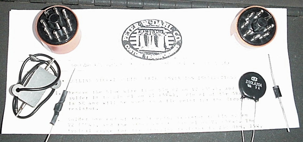
| Peter W. Dahl Co. Inc. makes a 5l6F-2 solid-state conversion kit (see figure 1). The current price is $34.95. It contains all of the above parts. In addition, the 5U4 and 5R4 solid-state replacements (octal plugs with solid state rectifiers) are already assembled. The kit is available from: |
|
Peter W. Dahl Co. Inc. 5869 Waycross Avenue El Paso, TX 79924 TEL: 915-751-2300 FAX: 915-751-0768 EMAIL: pwdco@pwdahl.com Peter W. Dahl Co. |
|
|
|||||||||||||
|
Click on image to enlarge and/or display in own window |
|
Figure 1 - The Peter Dahl Conversion Kit |
|
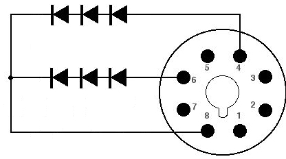
1). Install three diodes in series from pin #4 (anode of diodes) to pin #8
(cathode of diodes) of eight pin octal plug. See diagram 1. |
|
2). Install three diodes in series from pin #6 (anode of diodes) to pin #8
(cathode of diodes) of eight pin octal plug. See diagram 1. |
 |
|||||||||||||
|
Click on image to enlarge and/or display in own window |
|
Figure 2 - Tube replacements |
|
3). Repeat steps one and two to make a second octal plug. |
|
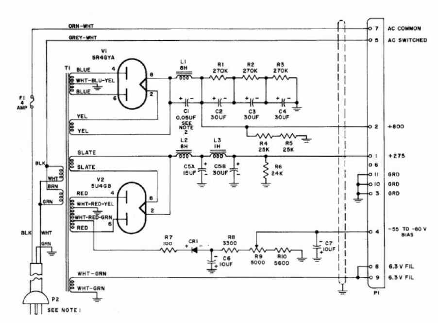
4). Remove the blue wire from pin #2 on V2 (5U4), and solder it to pin #1 on V1
(5R4). Pin #1 of the 5R4 is not used by the 5R4 or 516F-2. It will be used as a
tie point for the dropping resistor. |
|
5). Solder one end of the dropping resistor to pin #2 on V2 (5U4), and the other
end to pin #1 on V1 (5R4). The typical value for the dropping resistor is 200 Ohm,
25W. |
 |
|||||||||||||
|
Click on image to enlarge and/or display in own window |
|
Figure 3 - The Unaltered 516F-2 Power Supply |
|
6). Connect the MOV transient suppressor, Z130LA20A, across the transformer primary.
Use one side of the fuse, (Ring Section, NOT tip), and rear tie-point mounting strip
(the one with the two black wires on it). The Metal Oxide Arrestor (MOV) transient
suppressor is the one that looks like a small blue disc ceramic capacitor. This
will protect the transformer primary from line voltage surges. |
|
7). Replace the Selenium bias rectifier, CR1, with the Silicon diode, 1N5408, be
sure to observe the correct polarity. |
| 8). Plug the solid-state replacements for the 5U4 and 5R4 into their respective sockets. |
|
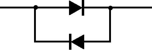
9). Attach the meter protector, (two 1N4007 diodes back-to-back in heat shrink
tubing), directly across the meter studs in the transceiver (KWM-2) or
transmitter (32S-1/3), whichever may be the case. This protects the meter from
slamming against the pin when first turned on. Leave any capacitor that may be
connected (shunt) across the meter studs. |
 |
|||||||||||||
|
Click on image to enlarge and/or display in own window |
|
Figure 4 - Meter Protection Circuit |
|
10). Check all of your wiring and make sure the modifications have been properly
installed before applying power. |
|
11). Connect all cables and switch power on. Adjust R-9 bias potentiometer (right
rear of the supply) for proper static current on the 6146's, (Approximately 40-50
Ma). |
 |
|||||||||||||
|
Click on image to enlarge and/or display in own window |
|
Figure 5 - The Modified 516F-2 Power Supply |
|
Version 3.0 - Copyright © 2004. John May, K6MAY. All Rights Reserved |
|
|
|
|
|
|
|
|